
You can connect two solar inverters in parallel only when both units are designed for parallel operation and configured according to the manufacturer’s manual. Parallel wiring is not a shortcut for mixing random inverters. The units must synchronize voltage, frequency, phase, communication, protection, and load sharing.
This guide explains the safe architecture. It is not a substitute for the current product manual or a qualified electrician. If you plan to parallel a specific Techfine model, confirm the exact wiring, communication cable, firmware, and settings from the latest manual before installation.
Key Takeaways
- Do not parallel arbitrary inverters; use models that explicitly support parallel operation.
- Victron’s parallel-system manual says units should match by device type, rating, firmware, and system voltage, with symmetrical AC/DC wiring and proper fusing (Victron Energy, updated 2026-03-04).
- A parallel inverter system needs communication/synchronization, not only L/N cable joining.
- For B2B projects, the installer manual, cable schedule, breaker list, and commissioning checklist should ship with every order.
Can Two Solar Inverters Be Connected in Parallel?
Yes, two solar inverters can be connected in parallel only if the inverter model supports parallel operation. Parallel-capable inverters use communication and control logic to keep output voltage, frequency, phase, and load sharing within a safe range.
The mistake is assuming that two AC outputs can simply be tied together. That can damage equipment and create a safety hazard. In a proper parallel system, the inverter manufacturer defines the topology, settings, cables, protection devices, and maximum number of units.
For importers, this is a documentation issue as much as a hardware issue. If a supplier says “parallel support,” ask for the exact parallel manual, accessory list, setting menu, and wiring diagram for the model being ordered.
What Must Match Before You Parallel Inverters?
Parallel inverters should normally be the same model, same power rating, same battery voltage platform, and compatible firmware version. The installation also needs matching AC output settings, supported communication cables, and protection devices sized for each unit.
| Pre-check | What to confirm | Why it matters |
|---|---|---|
| Model and rating | Same inverter model and output rating | Prevents uneven load sharing |
| Firmware/settings | Same approved firmware and parallel mode | Allows synchronization |
| Battery voltage | Same 24V/48V/other DC platform | Prevents DC-side mismatch |
| AC output | Same voltage, frequency, and phase mode | Prevents AC conflict |
| Communication | Correct parallel cable or port | Enables master/slave or load sharing |
| Protection | Separate DC/AC breakers or fuses where required | Isolates faults safely |
| Cable layout | Matched cable length and cross-section where manual requires | Reduces imbalance |
| Grounding/neutral | Local code and manual-approved method | Prevents shock and nuisance faults |
Victron’s VE.Bus manual gives a useful example of this discipline: parallel systems require matched devices, correct configuration, same DC system voltage, and symmetrical wiring practices (Victron Energy, updated 2026-03-04). The exact rules for Techfine or any other brand must still come from that brand’s current manual.
What Does a Safe Parallel Inverter Architecture Look Like?
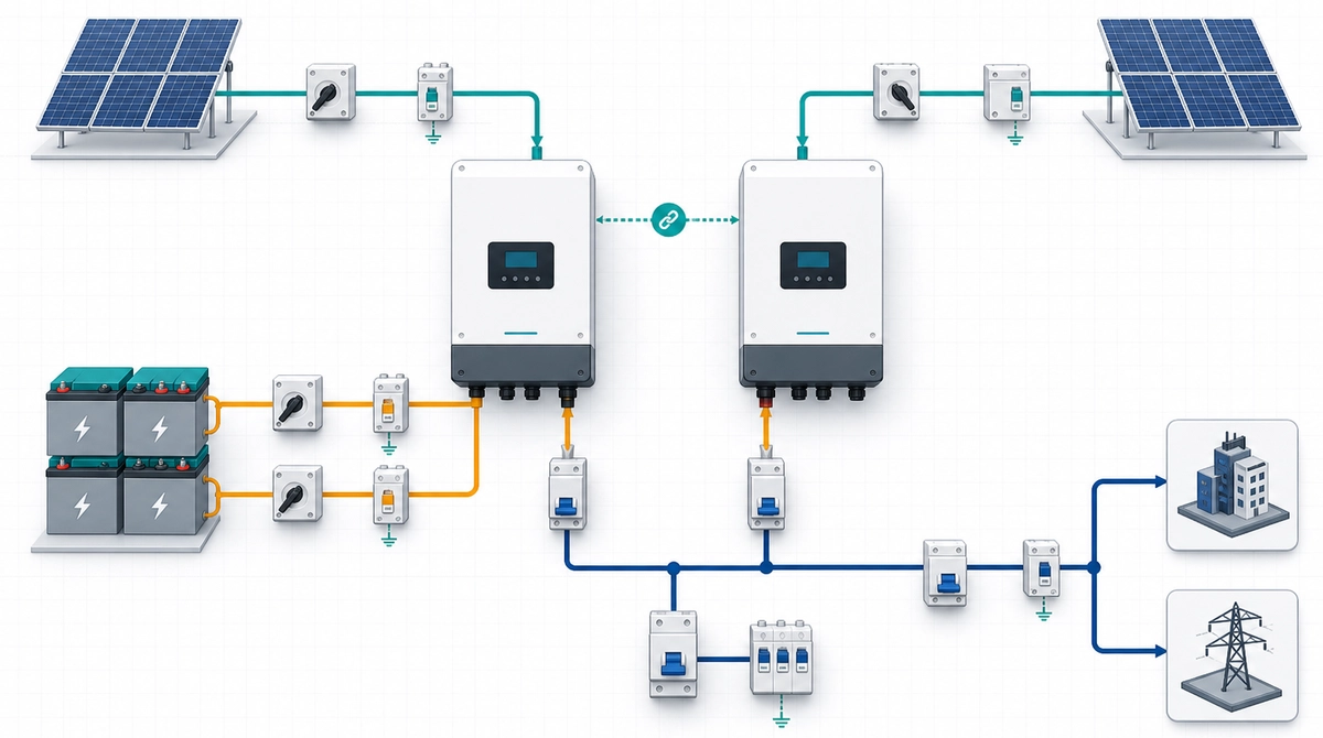
A safe parallel architecture connects each inverter through defined DC input protection, battery/busbar connections, communication links, and AC output protection before feeding the load panel. The communication link is the part many simple diagrams forget.
A generic two-inverter layout has these blocks:
- PV strings or PV combiner feeding each inverter according to its PV input rating.
- A battery bank or DC bus sized for total inverter current.
- DC breakers or fuses for each inverter.
- Parallel communication cable between inverters.
- AC output protection for each inverter, then a common distribution point if allowed.
- Load distribution panel with correct grounding and neutral arrangement.
- Monitoring or display setup to check load sharing and alarms.
Do not copy the terminal order from another brand’s diagram. Even two similar-looking hybrid inverters can use different neutral bonding, phase setup, parallel cards, or battery communication rules.
Step 1: Confirm Parallel Support in the Manual
The first step is not wiring; it is confirming that the exact inverter model supports the exact parallel mode you need. A model may support single-phase parallel but not split-phase, three-phase, or mixed-grid operation.
Check the manual for:
- maximum number of parallel units
- supported phase modes
- required communication cable or parallel board
- battery voltage and battery type limits
- PV input rules in parallel operation
- firmware/version requirements
- AC input and generator input rules
- neutral/grounding instructions
- commissioning order
If you cannot find those details, do not publish a model-specific wiring instruction. In an OEM/ODM project, ask the supplier for the latest PDF manual before the buyer places the order.
Step 2: Size the DC Side Before the AC Side
The battery and DC protection must support the combined current of both inverters, not only one inverter. Two 5.5kW inverters can create an 11kW AC system, but the battery cables, breakers, busbars, and battery BMS must all handle the resulting DC current.
For a 48V battery system, current rises quickly at high power. That is why installers should calculate battery-side current, surge current, cable length, voltage drop, breaker rating, and BMS discharge limit before wiring. A shared battery bank also needs balanced connections so one cable path does not carry more current than the other.
If the battery has communication with the inverter, confirm that the BMS can communicate correctly with the parallel inverter setup. A single battery communication cable may not behave the same way in a two-inverter layout.
Step 3: Use the Approved Communication and Settings
Parallel inverters need a control link so they can synchronize output and share load. The cable might be RS485, CAN, VE.Bus, or a brand-specific parallel cable, depending on the model.
Typical settings include:
- inverter ID or address
- master/slave or equal-parallel mode
- output voltage
- output frequency
- battery type and charge voltage
- maximum charge/discharge current
- grid or off-grid mode
- phase configuration, where supported
Set both inverters before connecting loads. Then test the system with no load, light load, and staged heavier loads. Watch whether both units carry load as expected. If one inverter carries most of the load, stop and check configuration, cabling, and firmware.
Step 4: Commission the System Before Handing It Over
Commissioning proves that the two inverters work as one system under real operating conditions. Skipping this step creates after-sales problems for distributors, especially in weak-grid markets where voltage changes and surge loads are common.
Use this checklist:
| Commissioning check | Pass condition |
|---|---|
| Visual inspection | Cable size, torque, polarity, and labeling checked |
| Communication | Both inverters detected in parallel mode |
| No-load startup | Stable voltage and frequency |
| Light-load test | Both units remain stable |
| Step-load test | No overload or load-sharing alarm |
| Battery charge test | Charge current stays inside BMS/inverter limits |
| Fault-code check | Display and manual match the observed status |
| Handover | Installer receives wiring diagram, settings, and alarm list |
For related troubleshooting, see our solar inverter problems and solutions guide and our display-code guide on how to read a solar inverter display.
When Is a Parallel Inverter System Worth It?
Parallel inverters make sense when a buyer needs more output power, redundancy, or modular expansion without moving to a single larger inverter. They are common in larger homes, small shops, clinics, farms, and weak-grid backup systems.
Parallel is not always the best choice. A single larger inverter may be cleaner when the load is simple. A three-phase inverter may be better for C&I loads. A split-phase model may be needed for 110/120Vac and 220/240Vac loads in parts of the Americas.
For battery voltage and smaller backup-system planning, compare this article with our 24V solar inverter setup guide. For wiring basics outside parallel systems, read how to properly set up an inverter connection.
FAQ: Connecting Two Solar Inverters in Parallel
Can I connect two different inverter brands in parallel?
Usually no. Parallel operation requires synchronization and communication defined by the manufacturer. Two different brands may look similar on the AC side, but their control logic, firmware, neutral rules, and fault handling can be incompatible. Use a manufacturer-approved parallel system.
Do both inverters need their own solar panels?
It depends on the model. Some parallel systems use separate PV inputs for each inverter. Others may have a shared DC source or battery-first architecture. Follow the manual’s PV input rules, including maximum voltage, current, polarity, and string layout.
Can two 5kW inverters make a 10kW system?
They can only do that if both units are designed and configured for parallel output. The battery, BMS, DC breakers, AC breakers, busbars, cables, and load panel must also be sized for the combined power. Do not assume the rating doubles safely without system-level checks.
Is parallel connection better than buying one larger inverter?
Not always. Parallel systems add communication, protection, and troubleshooting complexity. They are useful when modular expansion or redundancy matters. One larger inverter can be simpler if the load profile is clear and the product line supports that rating.
What should distributors request from the supplier?
Ask for the current model manual, approved parallel diagram, accessory list, communication cable type, maximum parallel quantity, firmware rules, fault-code list, and commissioning checklist. For OEM/ODM orders, include these documents in installer training, not only in the product carton.