
Setting up an inverter connection is electrical work. It requires planning the DC and AC paths, verifying polarity, sizing cables and protection, and testing the system before power-up. The most common field problems are not in the inverter — they are in the wiring, terminals, battery settings, and protection devices.
This guide is a reference for qualified installers and technicians who wire inverters into solar PV, battery, and backup systems. It does not replace the exact model manual, local electrical code, or the requirement for a licensed electrician where applicable.
Key Takeaways
- Plan the full DC and AC wiring before mounting the inverter: PV string, battery bank, AC output, protection, grounding, and cable routing.
- Verify polarity, cable size, torque, and protection ratings against the inverter manual and local code.
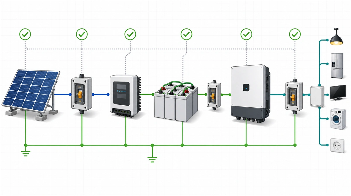
- Integrate batteries and controllers in the correct sequence: charge controller → battery → inverter DC input → AC output → loads.
- A wiring diagram in the manual is the final reference; the steps below are a general framework.
What Should Be Planned Before Connecting an Inverter?
Planning the wiring path and protection devices is more important than the physical connection step. A mistake at the planning stage — undersized cable, wrong protection rating, incorrect battery voltage — becomes a reliability problem after the system is commissioned.
Before connecting anything, confirm:
- Inverter model, DC input voltage range, PV input limits, AC output rating, and the exact terminal layout from the manual
- PV array configuration: series or parallel, total Voc adjusted for the lowest expected temperature
- Battery bank nominal voltage, chemistry, BMS communication type, and charge/discharge current limits
- AC load list with continuous and surge watts
- Cable sizes, lug types, torque values, and protection device ratings per the manual and local code
- Grounding scheme per the inverter manual and local regulations
For a full system sizing walkthrough, see how to calculate solar panel, battery, and inverter capacity.
DC-Side Connection: PV Array, Charge Controller, and Battery
The DC side is where polarity errors, undersized cable, and incorrect protection cause the most commissioning failures. Follow the exact sequence in the product manual and isolate all sources before making connections.
PV Array to Charge Controller
The charge controller sits between the PV array and the battery. Connect PV positive and negative to the controller’s PV input terminals, respecting polarity and the controller’s maximum PV input voltage and current limits. Size the PV cable for voltage drop over the full cable run.
Charge Controller to Battery
Connect the controller’s battery output terminals to the battery bank, respecting polarity. Use the cable size and protection specified in the controller and battery manuals. Confirm the controller’s battery type setting matches the installed battery chemistry before energizing.
Battery to Inverter DC Input
Connect the battery bank to the inverter’s DC input terminals. This is a high-current path; undersized cable or loose terminals will cause voltage drop, heat, and nuisance shutdowns. Use the terminal torque from the inverter manual and check for discoloration or heat at the first service visit.
For parallel inverter systems, see how to connect two solar inverters in parallel. For a 24V system example, see how to set up a 24V solar inverter system.
AC-Side Connection: Inverter Output to Loads
The AC side connects the inverter output to the building’s distribution board or dedicated backup circuit. The inverter’s AC output rating, the load breaker rating, the cable size, and the earthing system must be consistent.
- Use the AC output terminal block as shown in the manual; do not assume the terminal order from a different model.
- Size the AC cable and breaker for the inverter’s rated output current, not only the expected load.
- In grid-interactive or hybrid systems, follow the grid-connection and anti-islanding requirements of the local utility.
- Label circuits clearly so that future service visits know which loads are on the inverter output.
Common Commissioning Mistakes
Most commissioning faults are found in the wiring and settings, not in the inverter hardware. A systematic check before power-up prevents returns and site revisits.
| Mistake | What happens | How to prevent |
|---|---|---|
| Reversed DC polarity | Inverter may not start or may trip protection | Check polarity at every terminal point before energizing |
| Undersized battery cable | Voltage drop, heat, shutdown under load | Use cable size, lug, and torque from the manual |
| PV string Voc too high | MPPT input damage or shutdown | Calculate Voc at lowest expected temperature with margin |
| Battery type setting wrong | Poor charging, shortened battery life | Confirm chemistry and settings against the battery datasheet |
| AC earthing missing or incorrect | Safety risk and possible nuisance tripping | Follow the earthing scheme in the manual and local code |
| Loose terminal | Heat, arc, intermittent fault | Torque all terminals to the manual value; re-torque at first service |
Testing Before Full Power-Up
A staged power-up sequence isolates problems before they cascade. A common sequence is:
- With all sources off, visually inspect every terminal, cable route, protection device, and labeling.
- Energize the battery path first and confirm correct DC voltage at the inverter input terminals.
- Power on the inverter and check the display for normal startup and no immediate fault codes.
- Energize the PV input and confirm the controller or MPPT stage registers solar input.
- Energize the AC output with a small test load before connecting the full distribution board.
- Record the commissioning readings and take photos of the completed installation for service records.
For protection features to check during commissioning, see solar inverter protection overview.
Conclusion
A proper inverter connection is a planned, verified electrical installation. The most important steps are confirming polarity, cable sizing, protection ratings, battery settings, and a staged power-up sequence — all in strict reference to the exact model manual and local code.
Techfine supplies solar inverters for residential, commercial, and off-grid applications. For distribution and OEM/ODM projects, share the target system voltage, load profile, battery plan, and installation environment so we can support product matching and documentation.
Sources
- U.S. Department of Energy, Solar Integration: Inverters and Grid Services Basics, accessed July 2026.
- Exact wiring, torque, protection, earthing, and commissioning procedures must follow the specific inverter and component manuals and local electrical regulations.
FAQ: Inverter Connection Setup
Can I connect solar panels directly to a battery without a charge controller?
No. Connecting panels directly to a battery risks overcharging, gassing, and permanent battery damage. Always use a charge controller between the PV array and the battery, sized for the array’s voltage and current.
Does an inverter need a separate breaker on the AC side?
Yes. The AC output circuit needs overcurrent protection sized to the inverter’s rated output and the cable, per the manual and local electrical code. Do not rely only on the inverter’s internal protection.
What happens if battery polarity is reversed at the inverter input?
The inverter’s internal protection should block startup or trip, but some designs can be damaged by a sustained reverse-polarity connection. Always verify polarity with a multimeter before closing the DC breaker or isolator.
Can Techfine provide wiring diagrams for specific models?
Yes. For an OEM/ODM or distribution project, Techfine can provide model-specific installation documentation. Final wiring must still follow the exact manual and local electrical code for the installation country.