
Here is the rule that decides whether a 24V solar system works or fails on day one: series raises voltage, parallel raises capacity. Two 12V batteries in series make 24V. Batteries in parallel stay at 12V, no matter how many you add, and a 12V bank will not run a 24V inverter.
This guide builds a complete 24V system with four 12V lithium batteries (wired series-parallel for 24V and double capacity), solar panels matched to your charge controller type, and the cable and breaker sizes to tie it together safely.
Key Takeaways
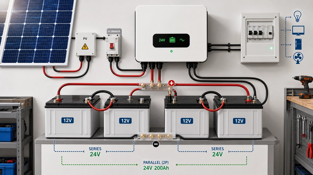
- Four 12V batteries for a 24V system are wired 2S2P: two pairs in series (24V each), then the pairs in parallel. Four 100Ah batteries give 24V 200Ah, about 4.8kWh.
- Series-connecting 12V lithium batteries requires packs of the same model, age, and charge state, and a BMS rated for series use. Confirm with the battery maker.
- Panel wiring depends on the controller: PWM wants panel voltage close to 30-40V for a 24V bank; MPPT accepts series strings (30-105V on typical built-in units).
- Fuses, correct cable gauge, and an air switch between every major component are not optional extras.
How a 24V Solar Inverter System Fits Together
Four components make up the system: solar panels generate DC, the charge controller (built into most hybrid inverters) manages battery charging, the battery bank stores energy at 24V, and the inverter converts 24V DC into AC for your loads. The inverter’s battery input voltage is fixed by design, which is why the battery bank must actually deliver 24V.
Why choose 24V at all? It’s the sweet spot for small-to-mid systems (roughly 1-3kW of load). Compared with 12V, it halves the current for the same power, which means thinner cables and cooler connections; compared with 48V, batteries and equipment are easier to source in many markets. If your loads will grow past ~3kW, consider starting at 48V; our MPPT controller sizing guide shows how system voltage drives current.
Battery Bank: Wiring Four 12V Batteries for 24V
Connect two 12V batteries in series to make one 24V pair, build a second identical pair, then connect the two pairs in parallel. This 2S2P layout delivers 24V with twice the amp-hours. With four 12V 100Ah lithium batteries, you get a 24V 200Ah bank, roughly 4.8kWh of storage.
Step by step:
- Pair 1 (series): battery A positive to battery B negative. A’s free negative and B’s free positive are now a 24V output.
- Pair 2 (series): repeat with batteries C and D.
- Parallel the pairs: connect the two 24V positives together and the two 24V negatives together, ideally through bus bars so both pairs share current evenly.
Three rules protect the bank:
- Match everything. Same model, same capacity, same age, and same state of charge before first connection. Charge each battery full individually before assembly; series-connecting a full and a half-empty lithium battery forces the BMS into constant imbalance.
- Confirm series capability. Many 12V LiFePO4 batteries allow 2 or 4 in series, but the limit is set by the BMS. Check the datasheet or ask the manufacturer before wiring in series.
- Never mix series and parallel on the same terminals. Complete each series pair first, then parallel the finished pairs.
Solar Panels: Series or Parallel Depends on Your Controller
With a PWM controller, keep panel voltage close to the battery charging range (about 30-40V input for a 24V bank), which usually means wiring panels in parallel. With MPPT, you can wire panels in series up to the controller’s input limit and let it convert the voltage down. This is the section where the controller type changes the wiring plan completely.
Using 36V/100W panels and a 1600W array as the worked example (matching typical built-in controllers on 24V low-frequency inverters):
| Built-in controller | PV input range | Recommended wiring for 16 × 100W (36V) panels |
|---|---|---|
| 60A PWM | 30-40V | All 16 panels in parallel (voltage stays ~36V) |
| 60A MPPT | 30-105V | 2 panels in series per string (~72V), 8 strings in parallel |
Series strings on MPPT carry real advantages: lower current means thinner PV cable, and higher voltage keeps the controller working earlier in the morning and later in the evening. Just verify the string’s open-circuit voltage, with a cold-weather margin of 10-12%, stays under the controller’s maximum input. Use MC4 connectors outdoors and keep strings identical (same panel count, same orientation).
Wiring Diagram and Assembly Order

Assemble in this order, with all breakers off:
- Prepare materials. 24V inverter, four matched 12V lithium batteries, panels, correctly sized cables, bus bars, fuses, and DC breakers (air switches).
- Build the battery bank (2S2P as above) and install a fuse or DC breaker on the main positive cable.
- Connect the battery bank to the inverter. Battery cables carry the highest current in the system; use the gauge the manual specifies and keep runs short.
- Wire the PV array per the table above, through its own DC breaker, then connect to the inverter’s PV input. Panels covered or connected last to avoid live DC work.
- Connect AC loads through an AC breaker panel. Power up in sequence: battery breaker first, then PV, then loads, starting small and watching the display.

The specification chart above gives cable gauge and breaker ratings by inverter size for 24V systems. When in doubt, size up the cable; undersized battery cable is the most common cause of voltage-drop shutdowns under heavy load. If you plan to run two inverters together later, that has its own rules; see how to connect two solar inverters in parallel.
Commissioning Checks and Maintenance
Before trusting the system, verify three numbers: battery bank resting voltage near 26.6-26.8V for a full LiFePO4 bank, PV input voltage within the controller’s range, and no breaker or terminal warming under load. Ten minutes with a multimeter here saves service calls later.
Ongoing care is modest: keep panels clean, re-torque terminals after the first month, watch the inverter’s display for fault codes (our display reading guide decodes them), and check battery balance every few months. If something misbehaves, work through the solar inverter problems and solutions guide before swapping parts.
FAQ: 24V Solar Systems
Can I get 24V by connecting 12V batteries in parallel?
No. Parallel connection keeps voltage at 12V and only adds capacity. To reach 24V you must connect two 12V batteries in series. For both more voltage and more capacity, use series-parallel: two series pairs, paralleled (2S2P).
Can I mix old and new batteries in a 24V bank?
Avoid it. The older battery’s higher internal resistance and lower capacity drag the whole bank down, and in series strings it forces BMS protection trips. Banks should be built from batteries of the same model, batch, and state of charge.
Do solar panels have to match the battery voltage?
Only with PWM controllers, which need panel voltage near the bank’s charging range. MPPT controllers accept a wide input window (30-105V on typical built-in units) and convert down, so series strings are fine and usually preferable.
How many watts can a 24V system handle?
Comfortably up to about 3kW of inverter load; beyond that, currents exceed 125A on the battery side and 48V becomes the better platform. For array sizing, a 24V bank pairs well with 800W-2000W of solar depending on the controller rating.
Can I add more batteries later?
Yes, in complete 24V pairs (never a single 12V unit), and realistically only within the first months. Adding brand-new pairs to a heavily cycled bank creates imbalance. If major expansion is likely, plan the final bank size, or the 48V step, from the start.
Where Techfine Fits
Techfine manufactures 24V and 48V hybrid and off-grid inverters with built-in PWM or MPPT charging, plus matched LiFePO4 batteries, as OEM/ODM product lines for distributors in load-shedding and weak-grid markets. If you’re assembling a 24V system kit for your market (inverter, batteries, wiring spec sheet, and packaging under your brand), tell us your target loads and monthly volumes and we’ll propose a configuration.